Are you tired of the confusion that comes with home wiring? Understanding the intricacies of electrical systems can be daunting, but with a clear switch board circuit diagram, you can simplify the process and take control of your home's electrical setup. In this blog post, we'll break down the essential components of a switch board circuit diagram, helping you visualize how electricity flows through your home. Whether you're a DIY enthusiast or just looking to better understand your home's wiring, this guide will equip you with the knowledge you need to make informed decisions and enhance your electrical safety. Let's dive in!
Electric Switch Board Diagram
An electric switchboard diagram is a crucial component in understanding and managing your home wiring system. This diagram visually represents the layout and connections of various electrical components, including circuit breakers, fuses, and switches, allowing homeowners to easily identify how electricity flows throughout their space. By familiarizing yourself with an electric switchboard diagram, you can simplify troubleshooting, enhance safety measures, and plan for future electrical upgrades or modifications. Whether you're a DIY enthusiast or just looking to improve your home's electrical efficiency, mastering the switchboard circuit diagram is an essential step in ensuring a safe and well-organized wiring system.
 wiringcourantes.z13.web.core.windows.net
 [solved]:
Understanding the switchboard circuit diagram is essential for anyone looking to simplify their home wiring. A well-organized switchboard not only enhances the safety and efficiency of your electrical system but also makes troubleshooting a breeze. By visualizing the connections between various components, such as switches, circuit breakers, and outlets, you can easily identify potential issues and make necessary adjustments. Whether you're a DIY enthusiast or a seasoned electrician, grasping the intricacies of a switchboard circuit diagram empowers you to optimize your home's electrical layout, ensuring both functionality and peace of mind. Dive into our comprehensive guide to learn how to decode these diagrams and elevate your home wiring project!
![[solved]:](https://i0.wp.com/media.cheggcdn.com/media/4e5/4e531f8a-870e-48a4-847b-16324b66a288/phpj3yIn5) www.solutionspile.com
www.solutionspile.com Simple House Wiring Diagram Exles
When it comes to understanding your home's electrical system, simple house wiring diagram examples can be incredibly helpful. These diagrams break down the complexities of wiring into easy-to-follow visuals, allowing homeowners to grasp how various components, such as switches, outlets, and circuit breakers, are interconnected. By studying these diagrams, you can gain insights into the layout of your switchboard and how to troubleshoot common issues. Whether you're planning a DIY project or just looking to enhance your knowledge about electrical systems, familiarizing yourself with these simple wiring diagrams can empower you to make informed decisions and ensure the safety and efficiency of your home's electrical setup.
 infoupdate.org
 Logic Circuit Schematic Diagram At Jennifer Colbert Blog
In the latest blog post on Jennifer Colbert's site, titled "Switch Board Circuit Diagram: Simplify Your Home Wiring!", readers are introduced to the essential concept of logic circuit schematic diagrams. These diagrams serve as a visual representation of the various components and connections in a circuit, making it easier for DIY enthusiasts and homeowners alike to understand and implement their wiring projects. By breaking down complex electrical systems into clear, manageable schematics, Jennifer empowers her audience to tackle home wiring with confidence, ensuring safety and functionality in every switchboard setup. Whether you're a seasoned electrician or a curious beginner, this guide provides valuable insights into the world of electrical circuits, helping you simplify your home wiring tasks with ease.
 storage.googleapis.com
 Draw Logic Circuit Diagram For The Following Boolean Expression A B C
In this section of our blog post titled "Switch Board Circuit Diagram: Simplify Your Home Wiring!", we will explore how to draw a logic circuit diagram for the Boolean expression ABC. This expression represents a simple AND operation, where the output is true only when all three inputs—A, B, and C—are true. To create the circuit diagram, start by placing three input terminals labeled A, B, and C. Then, connect these terminals to a single AND gate, which will serve as the output for the circuit. The output can be labeled as Z, representing the result of the AND operation. This straightforward logic circuit not only simplifies understanding but also enhances the efficiency of home wiring, making it easier to manage multiple switches and devices. By mastering such diagrams, homeowners can ensure their electrical systems are both functional and reliable.
 www.wiringdigital.com
 Other Wiring Gallery

www.caretxdigital.com
Switch Board Circuit Diagram
![[solved]:](https://i0.wp.com/media.cheggcdn.com/media/4e5/4e531f8a-870e-48a4-847b-16324b66a288/phpj3yIn5)
www.solutionspile.com
[solved]:

www.circuitdiagram.co
Three Phase Motor Wiring Diagram With Capacitor Start
www.wiringdigital.com
Wiring Diagram Of Electrical Panel

allwiringsketch.com
Wiring Diagram For Dip Switch: Simplify Your Connection

circuitdiagramtids.z21.web.core.windows.net
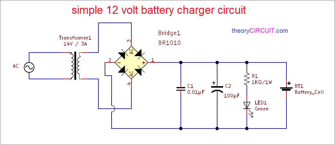
Free Battery Charger Circuit Diagram

wiringdiagramall.blogspot.com
House Wiring Diagram Single Phase

www.seekic.com
You Might Also Like: 2014 Jeep Wrangler Stereo Wiring
Simplify Principle Diagram Of Delta Transform Ups
