Dive into the fascinating world of audio amplification! Whether you're a seasoned audiophile or just starting to explore the intricacies of sound, understanding amplifier circuits is key to appreciating and customizing your audio experience. Let's explore a couple of examples showcasing different approaches to audio amplification.
40W+40W Audio Amplifier PCB: A Custom Solution

This image showcases a professionally manufactured PCBA (Printed Circuit Board Assembly) designed for a 40W+40W audio amplifier. What does that mean? Well, it signifies a dual-channel amplifier, each capable of delivering 40 watts of power. This type of amplifier is commonly used in stereo systems, providing distinct audio signals to the left and right speakers, creating a more immersive and spatially accurate soundstage.
The image highlights the complexity involved in modern circuit board design and manufacturing. Notice the densely packed components, meticulously arranged to optimize performance and minimize interference. The process involves more than just placing parts; it's a complex interplay of electrical engineering, materials science, and manufacturing expertise. Manufacturers specializing in PCBA offer custom solutions, tailored to specific requirements. They handle everything from the initial design and component sourcing to the final assembly and testing, ensuring a high-quality and reliable product.
The availability of custom PCBA services allows for the creation of specialized amplifiers to meet unique needs. For example, you might require an amplifier with specific filtering characteristics, impedance matching for particular speakers, or a compact design for a portable audio device. Custom PCBA ensures that the amplifier is perfectly tailored to the intended application, maximizing performance and efficiency.
LA4440 Bridge Stereo Amplifier Circuit Diagram

Moving from a complete manufactured solution, let's dive into a specific circuit diagram: the LA4440 bridge stereo amplifier. This schematic illustrates how the LA4440 integrated circuit can be configured to create a powerful stereo amplifier using the "bridge" configuration. The bridge configuration is a clever technique that allows for a greater voltage swing across the speaker, resulting in a higher output power compared to a standard single-ended amplifier configuration.
The LA4440 is a popular and versatile audio amplifier IC known for its simplicity and affordability. The circuit diagram reveals the essential components required to implement the amplifier: resistors, capacitors, and the LA4440 chip itself. Resistors are used to set the gain of the amplifier and provide bias currents, while capacitors serve to filter unwanted noise and couple the audio signal. The strategic placement and values of these components are crucial for achieving optimal performance and stability.
Analyzing the circuit diagram gives you insight into how the amplifier works. You can trace the signal path from the input to the output, observe how the components interact, and understand the function of each part. For example, the bridge configuration uses two LA4440 amplifier stages per channel, driven in opposite phase. This effectively doubles the voltage swing across the speaker, significantly increasing the output power. The capacitors play a critical role in blocking DC voltage and allowing only the AC audio signal to pass through.
Building an amplifier based on this circuit diagram is a great hands-on project for electronics enthusiasts and hobbyists. It allows you to put your knowledge into practice, gain a deeper understanding of amplifier design, and customize the amplifier to your specific needs. Understanding these circuit diagrams are the fundamentals for more advanced projects or even developing your own custom PCBAs.
If you are looking for 100w Audio Power Amplifier Circuit Diagram you've visit to the right page. We have 25 Pictures about 100w Audio Power Amplifier Circuit Diagram like Audio Amplifier Circuit Diagram Explanation » Wiring Diagram, 40 Watt Audio Amplifier Circuit and also Bass Boost Circuit Diagram for Amplifier. Here you go:
100w Audio Power Amplifier Circuit Diagram
 usermanualdoggiest.z21.web.core.windows.net
 How To Make 12v Audio Amplifier Circuit - Wiring Draw And Schematic
 www.wiringdraw.com
 Single Sided 4440 IC DIY Audio Boards 40 40W Amplifier Board, Rs 140
 www.indiamart.com
 amplifier 40w ic sided
TDA1514 40 Watt Audio Amplifier Circuit - ElectroSchematics.com
 www.electroschematics.com
 amplifier circuit 40w stereo watt electroschematics
40 Watt Audio Amplifier Circuit
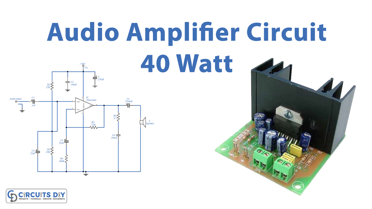 www.circuits-diy.com
 DIY Make Powerfull 12V 40W Audio Amplifier | How To Make Amplifier At
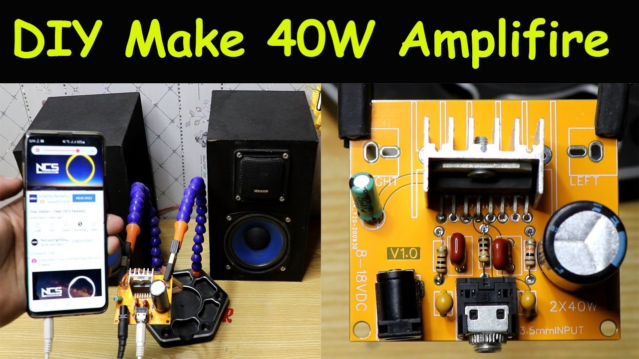 www.youtube.com
 Bass Boost Circuit Diagram For Amplifier
 www.pinterest.com
 DIY Subwoofer Amplifier Circuit Using TDA2030, How To Make Subwoofer
 www.pinterest.com
 Schuldgefühl Grenze Vorhang Hifi Verstärker Diy Lager Neuheit Allein
 iam-publicidad.org
 Audio Amplifier Circuit Diagram Explanation » Wiring Diagram
 www.organised-sound.com
 40W Audio Amplifier Based On TDA1514 - Amplifier Circuit Design
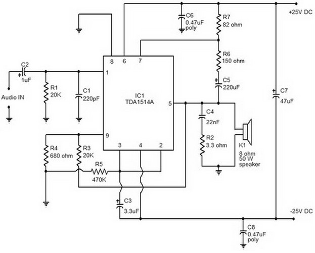 amplifiercircuit.net
 amplifier 40w
40W 4Ohm Audio Amplifier Board Buy In Bd On EEEShopBD
 eeeshopbd.com
 Jual Penguat Daya Audio Bluetooth Mobil Car Audio Power Amplifier 12V
 www.blibli.com
 Diy Audio Amplifier Circuit
 manualdbchipping.z21.web.core.windows.net
 40W
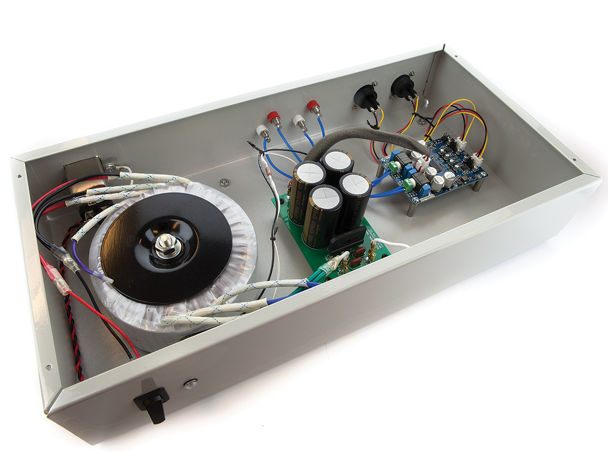
Audio Source Stereo Power Amplifier
 guidemanuallining.z21.web.core.windows.net
 40W+40W Audio Amplifier Pcb Manufacturer Pcba Assembly Custom Circuit
www.alibaba.com 40W Audio Amplifier With 2N3055 & MJ2955
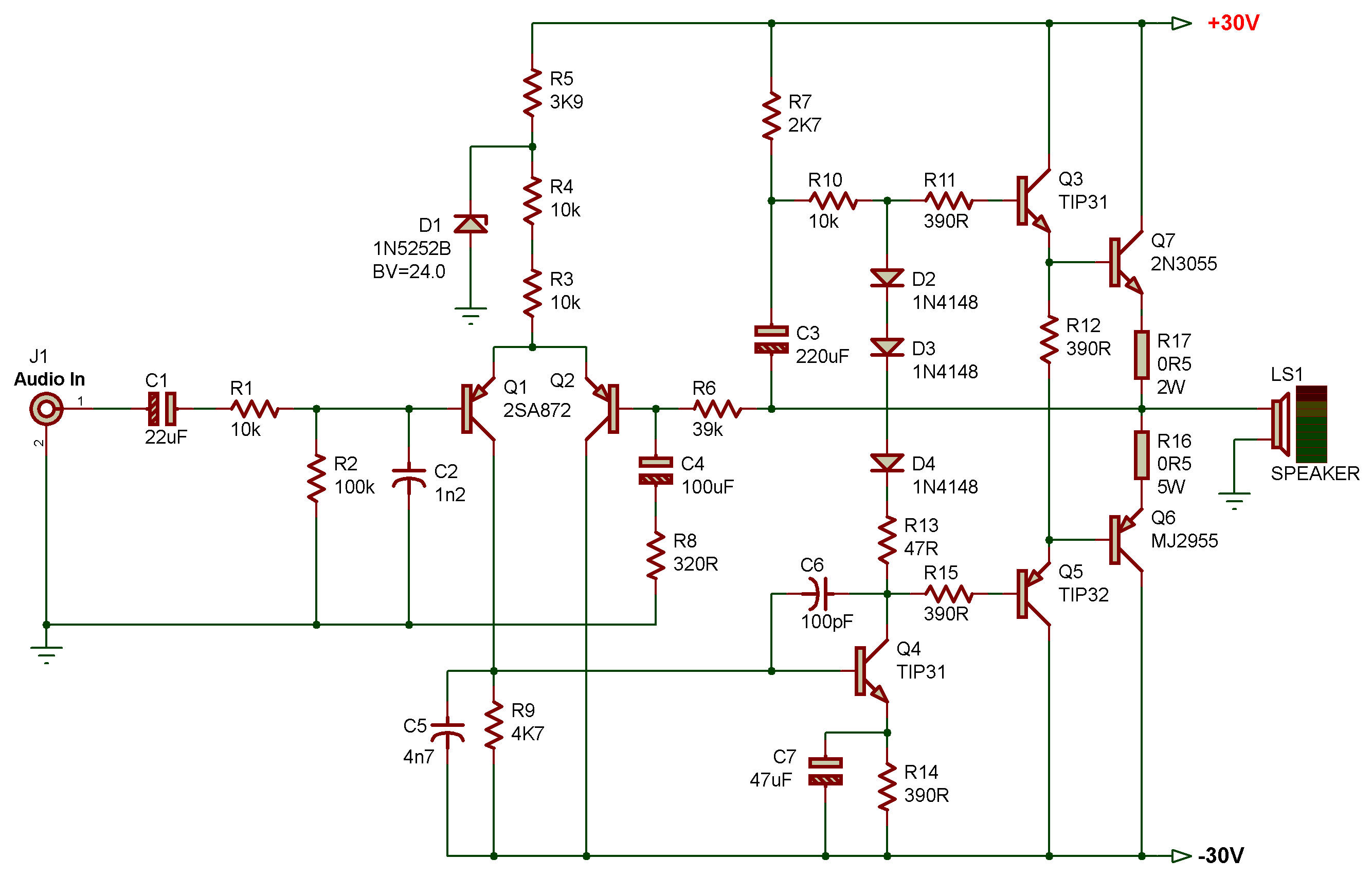 zpag.net
 amplifier 40w audio
DIY Simple Powerful Amplifier Using TDA2030, Homemade Amplifier 12V
 www.youtube.com
 Buy Diy Audio Amplifier Kit, Amp Board Digital HIFI Power Module PCB
 www.desertcart.lk
 40W Audio Amplifier (Step By Step) Make Very Easy - YouTube
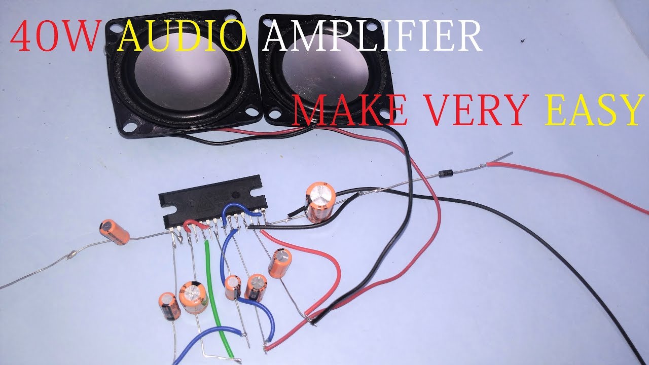 www.youtube.com
 amplifier 40w audio
Audio Amplifier Circuit Diagrams - Circuit Diagram
 www.circuitdiagram.co
 LA4440 Bridge Stereo Amplifier Circuit Diagram - TRONICSpro
tronicspro.com TDA1514 40 Watt Audio Amplifier Circuit - ElectroSchematics.com
 www.electroschematics.com
 amplifier pcb mono 40w watt 50w electroschematics placement wiring
LM2876 40W Audio Power Amplifier Circuit And Explanation | Electronic
 alectronicscircuits.blogspot.com
 amplifier circuit 40w puissance amplificateur explanation 12v circuits schema schematics genie electronique
Tda1514 40 watt audio amplifier circuit. Lm2876 40w audio power amplifier circuit and explanation. Audio amplifier circuit diagrams
: Simplify Your PCB Design!
2pc prototype pcb arduino uno r3 shield board module expansion diy inc")


