Diving into the fascinating world of RF amplifiers and audio circuits can seem daunting at first, but breaking down the schematic diagrams makes it much more approachable. Let's explore a couple of examples that highlight the intricacies and potential of these technologies.
RF Amplifier Schematic Diagram

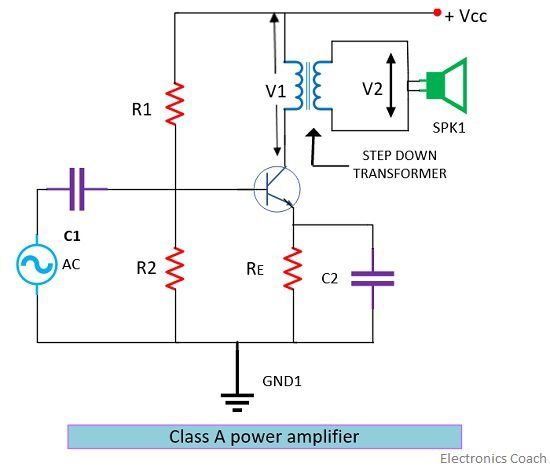
RF (Radio Frequency) amplifiers are crucial components in many communication systems, from your mobile phone to broadcast transmitters. They boost the power of radio signals, ensuring they can travel long distances or be processed effectively. Understanding the schematic of an RF amplifier involves recognizing key elements like transistors, inductors, capacitors, and resistors. Each plays a specific role in shaping the signal, controlling its frequency, and maximizing its amplification.
Transistors, often bipolar junction transistors (BJTs) or field-effect transistors (FETs), act as the active amplification elements. They take a small input signal and, using a DC power supply, produce a larger output signal. The configuration of these transistors (e.g., common emitter, common collector, common base for BJTs) influences the amplifier's characteristics like gain, impedance, and stability. Inductors and capacitors are used to create resonant circuits that tune the amplifier to a specific frequency range. These components are essential for matching impedances and filtering out unwanted noise, ensuring the amplifier operates efficiently and with minimal distortion.
Resistors play a vital role in setting the bias current for the transistors. This bias current ensures the transistors operate in their active region, providing linear amplification. Resistors are also used for feedback, which helps stabilize the amplifier and improve its linearity. A well-designed RF amplifier schematic balances these components to achieve the desired gain, bandwidth, and stability. Careful attention must be paid to component selection and layout to minimize parasitic effects and ensure optimal performance at high frequencies.
1000W Audio Amplifier Circuit Diagram

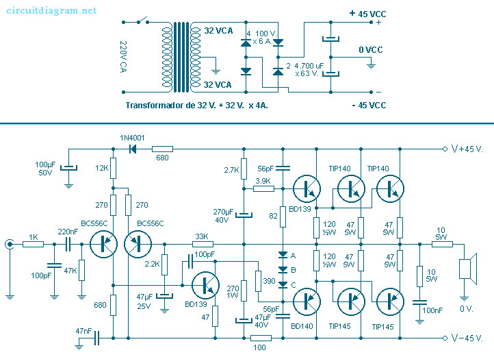
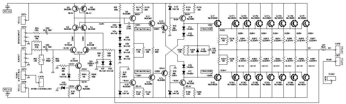
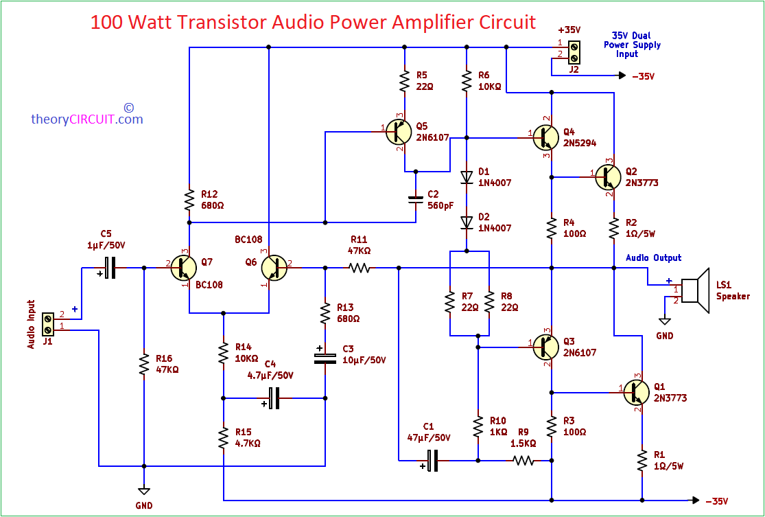
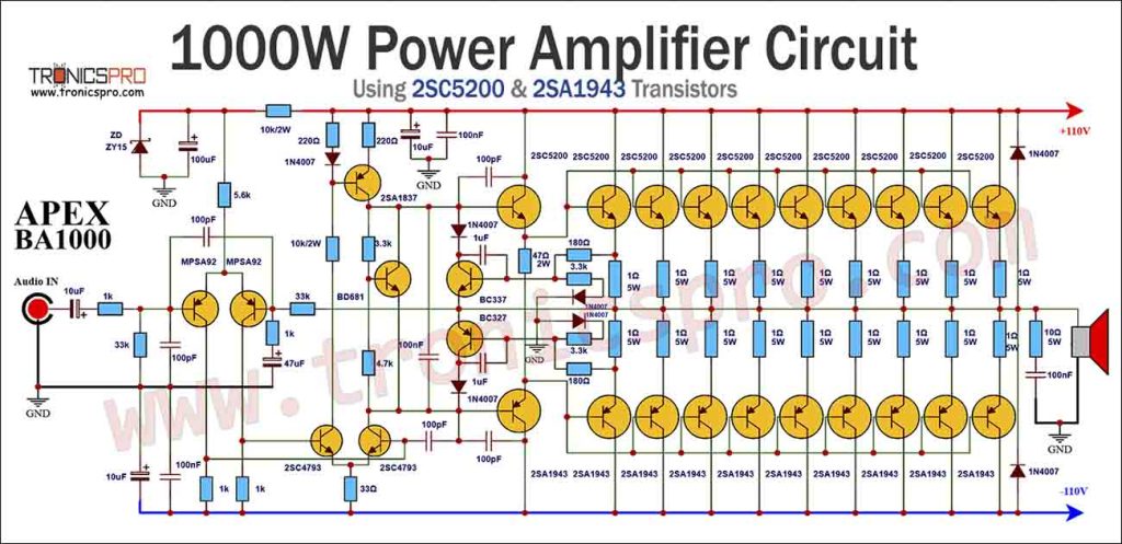
Moving into the realm of audio, the 1000W audio amplifier circuit showcases the power and precision needed to drive high-output speakers. This type of amplifier typically utilizes complementary pairs of high-power transistors, such as the 2SC5200 (NPN) and 2SA1943 (PNP), which are known for their robust performance and ability to handle large currents and voltages. The design often incorporates a push-pull configuration, where one transistor conducts during the positive half-cycle of the audio signal and the other conducts during the negative half-cycle.
The schematic diagram of a 1000W audio amplifier will include several stages. A preamplifier stage boosts the weak input signal to a level suitable for driving the main amplifier stage. This stage often uses operational amplifiers (op-amps) to provide high gain and low distortion. The driver stage then amplifies the signal further, preparing it for the output stage, which is responsible for delivering the high power required to drive the speakers. This output stage typically uses multiple pairs of transistors in parallel to distribute the load and ensure reliability.
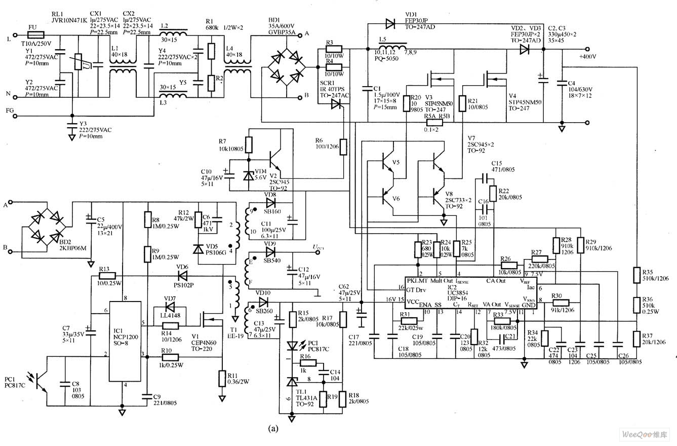
Protection circuitry is crucial in such a high-power amplifier. This includes overcurrent protection, which prevents damage to the transistors in case of a short circuit or excessive load, and thermal protection, which shuts down the amplifier if it overheats. The power supply is another critical aspect, as it must be able to provide the large currents needed to deliver 1000W of power. This often involves using a high-capacity transformer and large electrolytic capacitors to smooth out the DC voltage. Understanding these schematics allows enthusiasts and professionals to build, troubleshoot, and optimize high-performance audio systems.
If you are searching about 1000W Amplifier Circuit Diagram based 2SC5200 & 2SA1943 you've visit to the right place. We have 25 Pics about 1000W Amplifier Circuit Diagram based 2SC5200 & 2SA1943 like 400W Power Amplifier Circuit Diagram | Audio Amp - TRONICSpro, 1000W Stereo Audio Amplifier with Transistors 2SC5200 and 2SA1943 and also 1000W Amplifier Circuit Diagram based 2SC5200 & 2SA1943. Here it is:
1000W Amplifier Circuit Diagram Based 2SC5200 & 2SA1943
 tronicspro.com
 1000W Audio Amplifier Circuit Diagram Using 2SC5200 2SA1943 | Audio
jp.pinterest.com 1000w Class D Amplifier Circuit Diagram Lowest Price | Www.pinnaxis.com
 www.pinnaxis.com
 1000w Audio Amplifier Circuit Diagram
 ar.inspiredpencil.com
 1000W Audio Amplifier Circuit Diagram With 2SC5200 And 2SA1943 Transistors
 www.pinterest.com
 Class E Amplifier Circuit Diagram
 manuallibmongos.z19.web.core.windows.net
 A Comprehensive Guide To Rf Amplifier Schematic Diagrams: Everything
techschems.com 500W Amplifier Circuit Diagram 2SC2922 2SA1216 - TRONICSpro
 tronicspro.com
 400W Power Amplifier Circuit Diagram | Audio Amp - TRONICSpro
 tronicspro.com
 1000w Power Amplifier Circuit Diagram Using C5200 - TRONICSpro
 tronicspro.com
 1000w Power Amplifier Circuit Diagram Using C5200 - TRONICSpro
 tronicspro.com
 Terbaru 31+ 1000W Power Amplifier Circuit Diagrams
 skemadriver.blogspot.com
 circuit 1000w amplifier power diagram driver led output adjustable voltage seekic terbaru diagrams sagabio pcb sumber
1000w Mosfet Power Amplifier Circuit Diagram - Home Wiring Diagram
 homewiringdiagram.blogspot.com
 mosfet circuit amplifier diagram 1000w power audio
1000W Stereo Audio Amplifier With Transistors 2SC5200 And 2SA1943
 amplifiercircuit.net
 amplifier circuit watts 1000w amplificador watt transistor diagrama stereo circuito transistors hifi schematics circuitos speakers
1000 Watts Power Amplifier Circuit Diagram
 wirepartephemerous.z14.web.core.windows.net
 1000w Power Amplifier Circuit Diagram Using C5200 - TRONICSpro
 tronicspro.com
 Amplifier Circuits Diagram
 enginedbeuphonises.z21.web.core.windows.net
 Transformerless Power Amplifier Circuit Diagram - TRONICSpro
 tronicspro.com
 1000w Power Amplifier Circuit Diagram Using C5200 - TRONICSpro
 tronicspro.com
 1000w Audio Amplifier Circuit Diagram - Uploadist
 uploadist68.blogspot.com
 1000w Power Amplifier Circuit Diagram Pcb
 wiredatakatrinzh.z22.web.core.windows.net
 1000W Amplifier Circuit Using 2SC5200 2SA1943 - TRONICSpro
 tronicspro.com
 D718 Simple Amplifier Circuit Diagram For Beginners | DIY
 tronicspro.com
 New Power Amplifier Circuit Diagram Pin On Other Project's
 diagramabranar1ih.z21.web.core.windows.net
 1000W Power Amplifier Circuit 2SC5200 & 2SA1943 Apex BA1000
 tronicspro.com
 A comprehensive guide to rf amplifier schematic diagrams: everything. Mosfet circuit amplifier diagram 1000w power audio. Transformerless power amplifier circuit diagram
: Simplify Your PCB Design!
2pc prototype pcb arduino uno r3 shield board module expansion diy inc")


