Alright, let's dive into something a bit more technical today. We're going to explore the world of full-bridge inverters. Now, I know that might sound a bit intimidating at first, but trust me, once you grasp the fundamentals, it's actually quite fascinating. These circuits are essential components in converting DC power, like what you get from a battery, into AC power, which is what powers most of our appliances. Think solar panels feeding energy back into the grid, or an uninterruptible power supply (UPS) keeping your computer running during a blackout – full-bridge inverters are often at the heart of these systems.
Full Bridge Inverter

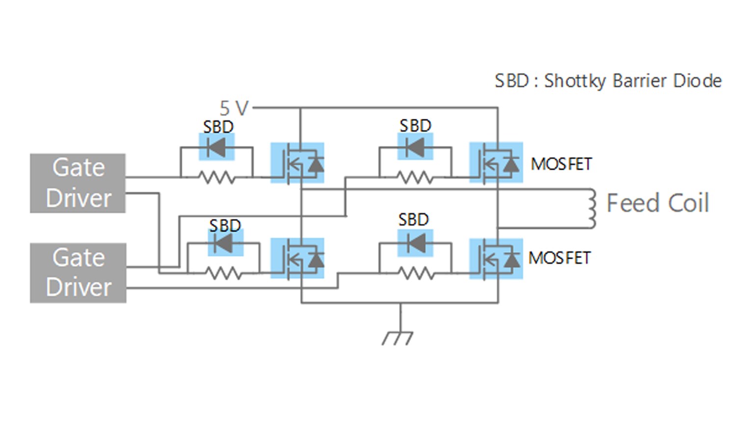
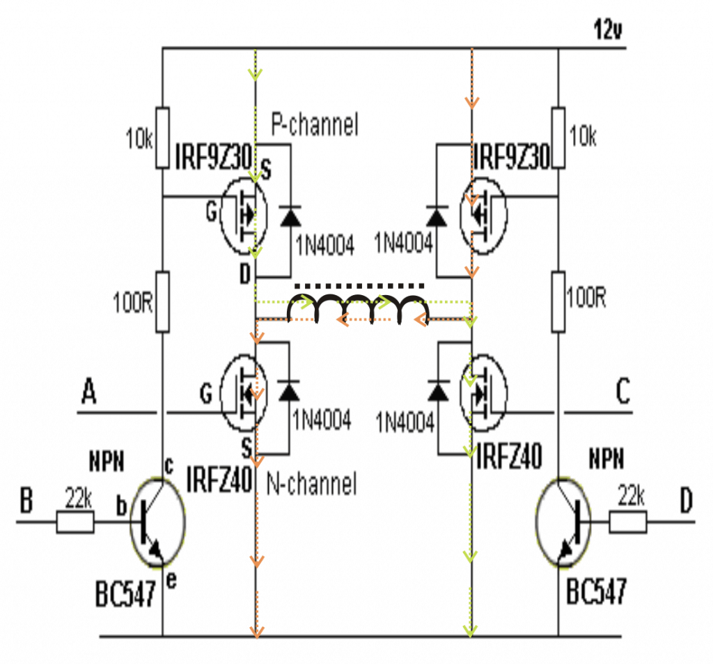
The basic concept behind a full-bridge inverter is elegantly simple. It uses four switches, typically transistors or MOSFETs, arranged in a bridge configuration. By strategically switching these transistors on and off in a specific sequence, we can reverse the polarity of the DC input voltage, effectively creating an alternating current output. The frequency of this AC output is determined by the switching speed of the transistors. The faster they switch, the higher the output frequency. Different control techniques can be applied to these switches to achieve various outputs, such as sinusoidal or square wave.
There are several factors to consider when designing or working with full-bridge inverters. One crucial aspect is the selection of the switching devices. We need to choose transistors or MOSFETs that can handle the required voltage and current levels, and that have sufficiently fast switching speeds. Heat dissipation is also a major concern, especially at higher power levels. Efficient heat sinks and cooling methods are often necessary to prevent overheating and component failure. Additionally, proper gate driving circuitry is essential to ensure that the transistors switch cleanly and reliably.
Sg3525 Full Bridge Inverter Circuit - vrogue.co
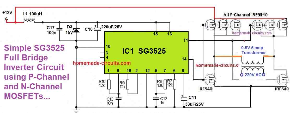
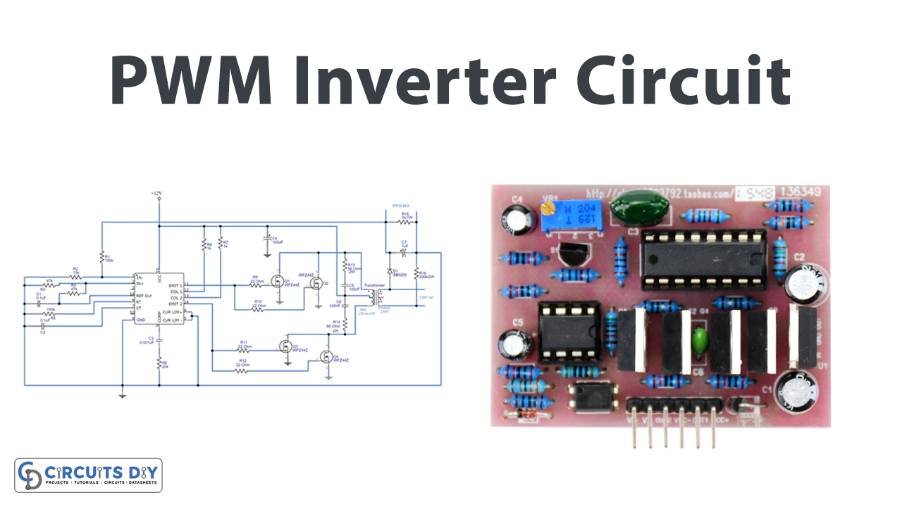
The SG3525 is a popular PWM (Pulse Width Modulation) controller IC often used in full-bridge inverter designs. The IC simplifies the control circuitry by providing all the necessary functions for generating the switching signals. Looking at this schematic, you can see how the SG3525 drives the gates of the P-channel MOSFETs. Using P-channel MOSFETs allows for a simpler high-side driver implementation. Pulse width modulation is a technique where the width of the pulse is varied to control the average voltage delivered to the load. This allows for efficient control of the AC output voltage. This particular design showcases the integration of the SG3525 to manage the switching of the bridge, demonstrating a more refined approach to inverter control. It showcases some level of sophistication.
Full-bridge inverters are incredibly versatile and find applications in a wide range of power electronic systems. From small portable inverters that power your laptop in your car to large-scale grid-tied inverters in solar power plants, the fundamental principles remain the same. Understanding the intricacies of these circuits is crucial for anyone working in the field of electrical engineering or renewable energy. They continue to evolve, with advancements being made in switching technologies, control algorithms, and efficiency improvements. As our demand for clean and efficient power continues to grow, full-bridge inverters will undoubtedly play an increasingly important role in shaping our energy landscape.
If you are searching about 12 Volt 1000 Watt Power Inverter Design Process | GoHz.com you've visit to the right place. We have 25 Pictures about 12 Volt 1000 Watt Power Inverter Design Process | GoHz.com like Single Phase Inverter Design & Open loop Simulation in MATLAB. - YouTube, DIY H Bridge Circuit for Inverters || Convert DC to AC using this and also 152 final project- Full Bridge Inverter. Read more:
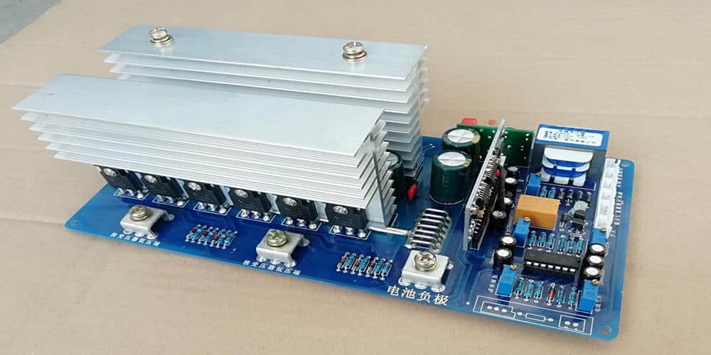
12 Volt 1000 Watt Power Inverter Design Process | GoHz.com
 www.gohz.com
 inverter 12v power board 1000w design circuit pcb dc converter frequency 1000 volt sine high 300w motherboard wave pcba watt
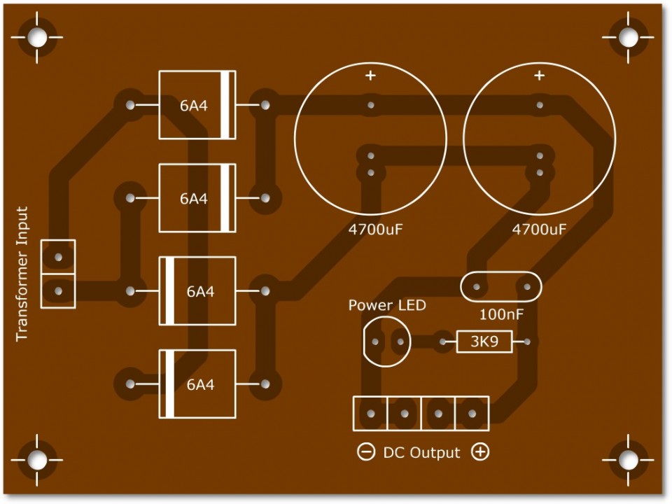
5A Full Wave Bridge Rectifier Power Supply PCB, 5A Power Supply PCB
 projectpoint.in
 pcb rectifier
10: Full Bridge Inverter PCB | Download Scientific Diagram
 www.researchgate.net
 Inverter Pcb Board Circuit Diagram Pdf - Wiring Digital And Schematic
 www.wiringdigital.com
 Full Bridge Mosfet Driver Schematic - Ftgreenway
 ftgreenway352.weebly.com
 H Bridge Inverter Circuit Design Manual - Wiring View And Schematics
 www.wiringview.co
 Inverter PCB - An In-depth Guide To The Heart Of Your Inverter - PCBA
 www.pcba-manufacturers.com
 Inverter Circuit Board: Cost, Benefits, And Applications – Hillman
 pcb-design.pages.dev
 Inverter PCB Everything It Entails – Hillman Curtis: Printed Circuit
 hillmancurtis.com
 Sg3525 Full Bridge Inverter Circuit - Vrogue.co
www.vrogue.co Pure Sine Wave Inverter | Inverter PCB | H-Bridge Inverter PCB | Pure
 www.pinterest.com
 inverter pcb sine wave
Full Bridge Inverter
www.deepakkumaryadav.in Inverter Pcb – Professional PCB Fabrication And PCB Assembly Service
 www.intopcb.com
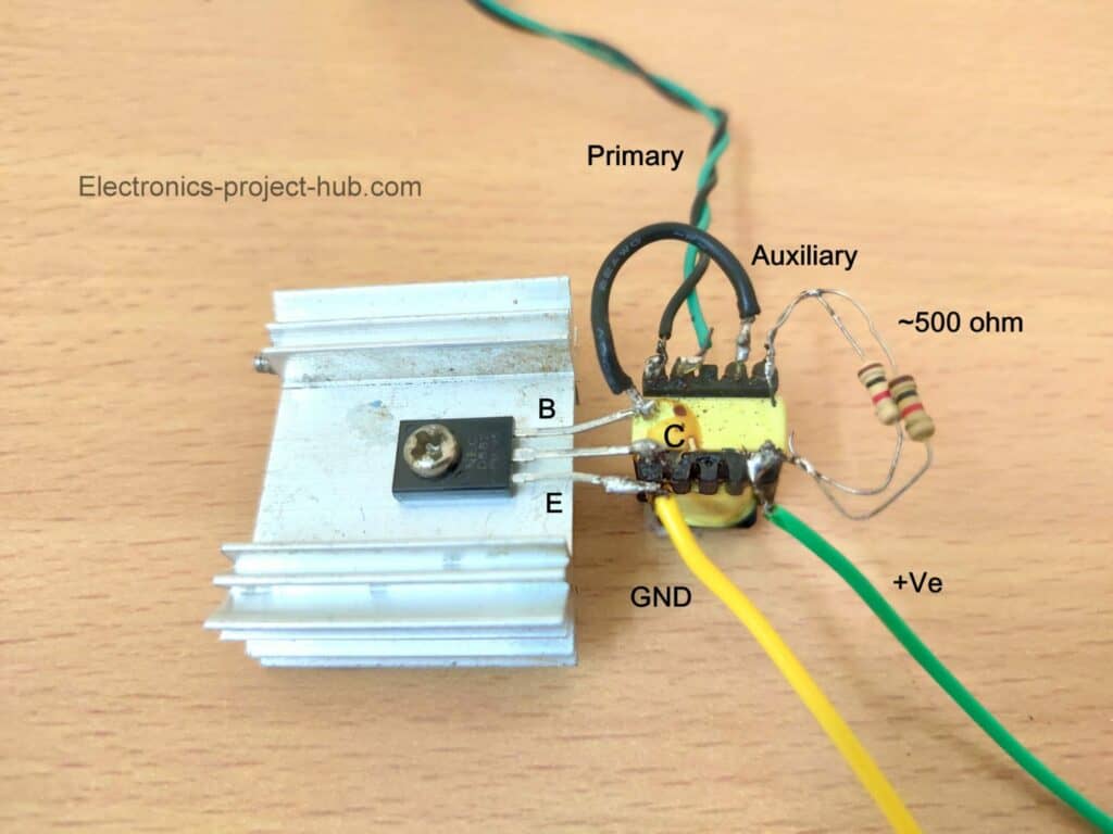
 DIY H Bridge Circuit For Inverters || Convert DC To AC Using This
 www.youtube.com
 circuit using convert inverters
The PCB Schematic For The H-Bridge Inverter | Download Scientific Diagram
 www.researchgate.net
 Igbt Inverter Schematic
 www.circuitdiagram.co
 Inverter Circuit Using Ic Sg3524 - Vrogue.co
 www.vrogue.co
 Single Phase Inverter Design & Open Loop Simulation In MATLAB. - YouTube
 www.youtube.com
 inverter matlab loop
HOW INFRASTRUCTURE CAN BECOME REBORN BY BECOMING BORN ROBUST FOR THE
 incose.onlinelibrary.wiley.com
 Full Bridge Circuit Diagram
 guidefixblogikar.z4.web.core.windows.net
 9: Full Bridge Inverter PCB Design | Download Scientific Diagram
 www.researchgate.net
 152 Final Project- Full Bridge Inverter
 web.stanford.edu
 full inverter bridge spice final project dc converter simulation fig
Digital Inverter Circuit Design
 wiringmanualgrandmamas.z21.web.core.windows.net
 Everything To Know About Inverter PCB Why So Important ? - Jarnistech
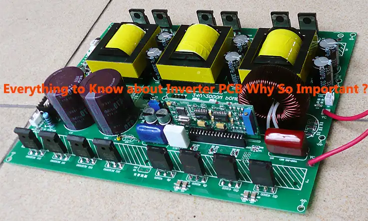 www.jarnistech.com
 Inverter Pcb Layout Archives | Viasion
 www.viasion.com
 12 volt 1000 watt power inverter design process. Sg3525 full bridge inverter circuit. Pure sine wave inverter
: Simplify Your PCB Design!
2pc prototype pcb arduino uno r3 shield board module expansion diy inc")


