Navigating the world of tractor wiring can sometimes feel like trying to decipher an ancient language. One component that often causes confusion is the ignition switch. Understanding how it’s wired is crucial for getting your John Deere up and running, whether you're tackling farm chores or restoring a vintage beauty. Let's dive into some helpful diagrams to demystify the ignition switch wiring on your John Deere tractor.
John Deere Ignition Switch Wiring Diagram - A Visual Guide

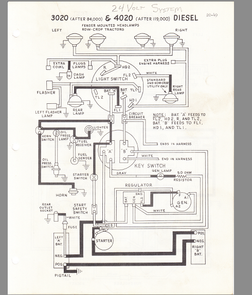
This diagram provides a general overview of a John Deere ignition switch wiring setup. Note the connections for the battery, starter, accessories, and ignition. Each terminal has a specific purpose, and ensuring the correct wires are connected to the right terminals is vital for proper operation. A common issue is confusing the battery terminal with the starter terminal. This can lead to a blown fuse or even damage to the starter solenoid. Carefully inspect the terminals and trace the wires back to their source to confirm correct placement. Also, check the diagram against your specific tractor model, as subtle variations exist. For example, some older models might use a different terminal configuration or have additional safety circuits incorporated into the ignition system. The image illustrates a common arrangement, with clearly labeled terminals. Remember that the gauge of the wire used is also critical. Using too thin a wire can result in voltage drop and overheating, especially on the starter circuit. Always consult your owner's manual or a qualified mechanic if you are uncertain about any aspect of the wiring. Proper grounding is also essential. A poor ground connection can lead to intermittent starting problems and can also damage other electrical components. Clean any corroded ground connections and ensure they are securely attached to the tractor's frame.
John Deere 2010 Ignition Switch Wiring Diagram - Specific Model Insights

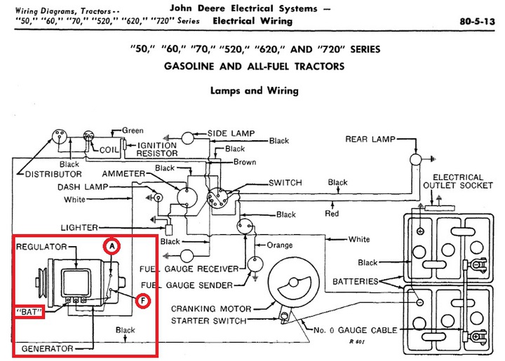
This diagram focuses specifically on the John Deere 2010 model. This model, popular for its versatility and robust design, has a particular ignition switch wiring configuration. Pay close attention to the placement of the resistor wire, which is often used to reduce voltage to the ignition coil once the engine is running. This wire is crucial for extending the life of the points and condenser in the ignition system. Without it, the ignition coil could overheat and fail prematurely. This image shows a slightly different terminal arrangement compared to the previous generic diagram. This highlights the importance of using the correct wiring diagram for your specific tractor model. Notice the labeling of each terminal; some models use letter designations (e.g., B, S, I, A), while others use numerical designations (e.g., 1, 2, 3, 4). Understanding these designations is key to properly connecting the wires. Before beginning any wiring work, disconnect the battery to prevent accidental shorts and electrical shocks. Take photographs of the existing wiring before disconnecting anything, as this can serve as a valuable reference when reassembling the connections. If you find any damaged or frayed wires, replace them immediately with wires of the same gauge and type. Use appropriate crimp connectors and heat shrink tubing to ensure secure and weatherproof connections. A well-maintained ignition system is the heart of your tractor's electrical system. Proper wiring not only ensures reliable starting but also contributes to the overall safety and performance of your machine.
If you are looking for John Deere 2010 Ignition Switch Wiring Diagram you've came to the right place. We have 25 Pictures about John Deere 2010 Ignition Switch Wiring Diagram like John Deere 4010 Ignition Switch Wiring | Lara Circuit, Wiring Diagram for John Deere 4010 Ignition Switch and also John Deere 1010 Ignition Switch Wiring Diagram - Wiring Flow Schema. Here it is:
John Deere 2010 Ignition Switch Wiring Diagram
stewart-switch.com John Deere 1010 Ignition Switch Wiring Diagram - Wiring Flow Schema
 www.flowschema.com
 John Deere 1010 Ignition Switch Wiring Diagram - Wiring Flow Schema
 www.flowschema.com
 John Deere Ignition Switch Wiring Diagram - Wiring Site Resource
wiringdatabaseinfo.blogspot.com John Deere 4020 Ignition Switch Wiring
 mungfali.com
 [DIAGRAM] John Deere 4010 Wiring Diagram - MYDIAGRAM.ONLINE
![[DIAGRAM] John Deere 4010 Wiring Diagram - MYDIAGRAM.ONLINE](https://lh3.googleusercontent.com/blogger_img_proxy/AEn0k_vtpH08yon-IVVcuhSXmDhp_2TGEHtKSiFS46AYLobFIuqWtXPP4hmjGY1KqwTST1ml6OvPy_IJARPj5QdnUIpKSurq3kJAowlSYFwUqdfhgVEw2Og8iwuM04C7I5jH_Fnm0h1NlB5zjmfTp-YaR-kj=s0-d) mydiagram.online
mydiagram.online John Deere 4010 Wiring Diagram
 wiringall.com
 wiring deere diagrams
John Deere Ignition Switch Wiring Diagram - Questinspire
John Deere Ignition Switch Wiring
 resolutionsforyou.com
 John Deere 4010 Wiring Diagram
 wiringall.com
 deere distribute companion neighborhood
John Deere 4010 Wiring Diagram
 wiringall.com
 deere
John Deere 4010 24 Volt Wiring Diagram - Wiring Diagram And Schematic
 wiring.hpricorpcom.com
 deere wiring schematic
The Complete Guide To John Deere Ignition Wiring: Tips And Troubleshooting
 elecschem.com
 John Deere Ignition Switch Wiring
 resolutionsforyou.com
 John Deere 4010 24 Volt Wiring Diagram - Wiring Diagram And Schematic
wiring deere 4010 volt starter 12v 24v battery instructables sel harness diagrams generator
John Deere 4010 24 Volt Wiring Diagram - Wiring Diagram And Schematic
 wiring.hpricorpcom.com
 4010 deere wiring volt schematics
Wiring Diagram For John Deere 4010 Ignition Switch
 johndocs.com
 John Deere 4010 24 Volt Wiring Diagram
 wiring.hpricorpcom.com
 John Deere 4010 24 Volt Wiring Diagram
 wiring.hpricorpcom.com
 John Deere Ignition Switch Wiring
 resolutionsforyou.com
 John Deere 4010 24 Volt Wiring Diagram - Wiring Diagram And Schematic
 wiring.hpricorpcom.com
 4010 deere volt jd system
John Deere 1010 Ignition Switch Wiring Diagram - Wiring Flow Schema
 www.flowschema.com
 John Deere 4020 Ignition Switch Wiring
 mungfali.com
 John Deere 1010 Ignition Switch Wiring Diagram - Wiring Flow Schema
 www.flowschema.com
 John Deere 4010 Ignition Switch Wiring | Lara Circuit
 lara-circuits.blogspot.com
 The complete guide to john deere ignition wiring: tips and troubleshooting. John deere ignition switch wiring diagram. John deere 4010 24 volt wiring diagram
: Simplify Your PCB Design!
2pc prototype pcb arduino uno r3 shield board module expansion diy inc")


